PLC — Programmable Logic Controllers
Programmable Logic Controllers
A Programmable Logic Controller (PLC) is a ruggedised digital industrial computer designed to continuously monitor inputs and make decisions to control outputs in real time. PLCs are the backbone of ISA-95 Level 1 control — found in virtually every automated production facility worldwide.
What Is a PLC?
A PLC is a solid-state industrial control system that executes a stored program to control industrial machinery and processes. Unlike a general-purpose PC, it is designed for harsh industrial environments: extreme temperatures, electrical noise, vibration, and humidity. The PLC continuously executes a scan cycle — reading inputs, executing the control program, and updating outputs — hundreds of times per second.
PLCs replaced electromechanical relay panels starting in the late 1960s. They offer the same ladder-logic programming paradigm but with the ability to reprogram without rewiring, self-diagnostics, and communication capabilities.
Brief History
Dick Morley (Bedford Associates) invents the first PLC — Modicon 084 — for General Motors. Replaces relay cabinets.
Modicon introduces Modbus protocol, the first industrial communication standard for PLCs.
Allen-Bradley introduces the PLC-3 with remote I/O capability; Siemens releases the SIMATIC S5 series.
IEC 61131-3 published — standardises 5 PLC programming languages (LD, FBD, ST, IL, SFC).
Ethernet-based fieldbuses (PROFINET, EtherNet/IP) begin displacing serial fieldbus protocols.
IEC 61131-3 3rd edition adds object-oriented extensions; IL language deprecated.
Software PLCs, cloud-connected edge PLCs, and AI-assisted programming tools emerge (IIoT era).
Hardware Architecture
A modern PLC is a modular system. The core modules communicate over a high-speed internal backplane bus. This modularity allows systems to be sized from a few I/O points (nano PLCs) to thousands of I/O points (rack-based systems).
IEC 61131-3 Programming Languages
The IEC 61131-3 standard (1993, revised 2013) defines five programming languages for PLCs, enabling code portability across vendors. All five languages can coexist within a single project, each used where it is most appropriate.
| Language | Type | Best For | Status |
|---|---|---|---|
| Ladder Diagram (LD) | Graphical | Discrete I/O, relay replacement, North American industry | Active |
| Function Block Diagram (FBD) | Graphical | Process control, signal flow, continuous systems | Active |
| Structured Text (ST) | Textual | Complex algorithms, data processing, strings, maths | Active |
| Sequential Function Chart (SFC) | Graphical | Sequential batch processes, state machines | Active |
| Instruction List (IL) | Textual | Low-level mnemonic (legacy only) | Deprecated |
The PLC Scan Cycle
The PLC executes its program in a continuous, deterministic loop called the scan cycle. Unlike event-driven computing, the PLC processes its entire program every cycle, regardless of whether inputs have changed. This guarantees deterministic behaviour critical for safety and process control.
All physical input states are copied to the Process Image Input (PII) table in RAM. The program works from this snapshot throughout the cycle.
The CPU processes all program instructions (ladder rungs, function blocks, ST statements) sequentially, reading from PII and writing results to Process Image Output (PIQ).
The PIQ table is transferred to the physical output modules, activating solenoids, drives, and other actuators.
The CPU processes pending communication requests: HMI data exchange, fieldbus messages, remote I/O updates, peer-to-peer messaging.
The OS checks memory integrity, watchdog timer, module health, and system housekeeping. If a fault is detected, the PLC halts and generates an alarm.
Major PLC Manufacturers
| Vendor | Product Family | Protocol Ecosystem | Market Strength |
|---|---|---|---|
| Siemens | SIMATIC S7-1200 / S7-1500 | PROFINET · PROFIBUS · OPC-UA | Europe, Automotive, Process |
| Rockwell Automation | Allen-Bradley ControlLogix / CompactLogix | EtherNet/IP · DeviceNet | North America, Discrete Mfg. |
| Mitsubishi Electric | MELSEC iQ-R / Q / L series | CC-Link IE · SLMP | Asia-Pacific, Automotive |
| Omron | SYSMAC NX / NJ / CP series | EtherCAT · EtherNet/IP | Asia, Packaging, Robotics |
| ABB | AC500 / AC500-S (Safety) | PROFINET · Modbus · OPC-UA | Energy, Marine, Process |
| Schneider Electric | Modicon M340 / M580 | EtherNet/IP · Modbus TCP | EMEA, Buildings, Water |
| Beckhoff | CX / EK / TwinCAT Software PLC | EtherCAT · OPC-UA | Machine builders, IIoT |
| B&R Automation | X20 / X90 / Power Panel | POWERLINK · OPC-UA | Motion, Plastics (ABB Group) |
PLC vs DCS vs SCADA — Key Differences
| Feature | PLC | DCS | SCADA |
|---|---|---|---|
| Primary Use | Discrete / sequential control | Continuous process control | Supervisory monitoring & control |
| Response Time | 1–100 ms | 100 ms–1 s | 1–60 s (operator-driven) |
| Architecture | Centralised or distributed | Distributed control stations | Central server with remote RTUs/PLCs |
| Programming | IEC 61131-3 (LD/FBD/ST) | Proprietary + IEC 61131-3 | Graphical scripting (VBA/Python) |
| I/O Scale | Tens to thousands of I/O | Hundreds to tens of thousands | Thousands via remote RTUs |
| Cost | Low–Medium | High | Medium–High (software) |
| Redundancy | Optional (hot-standby) | Built-in by design | Software/server redundancy |
| Industry | Manufacturing, machine OEM | Oil & Gas, Chemical, Power | Water/Wastewater, Pipeline, Utilities |
Typical PLC Applications
Industrial Control Panel Schematic (Technical Descriptions)
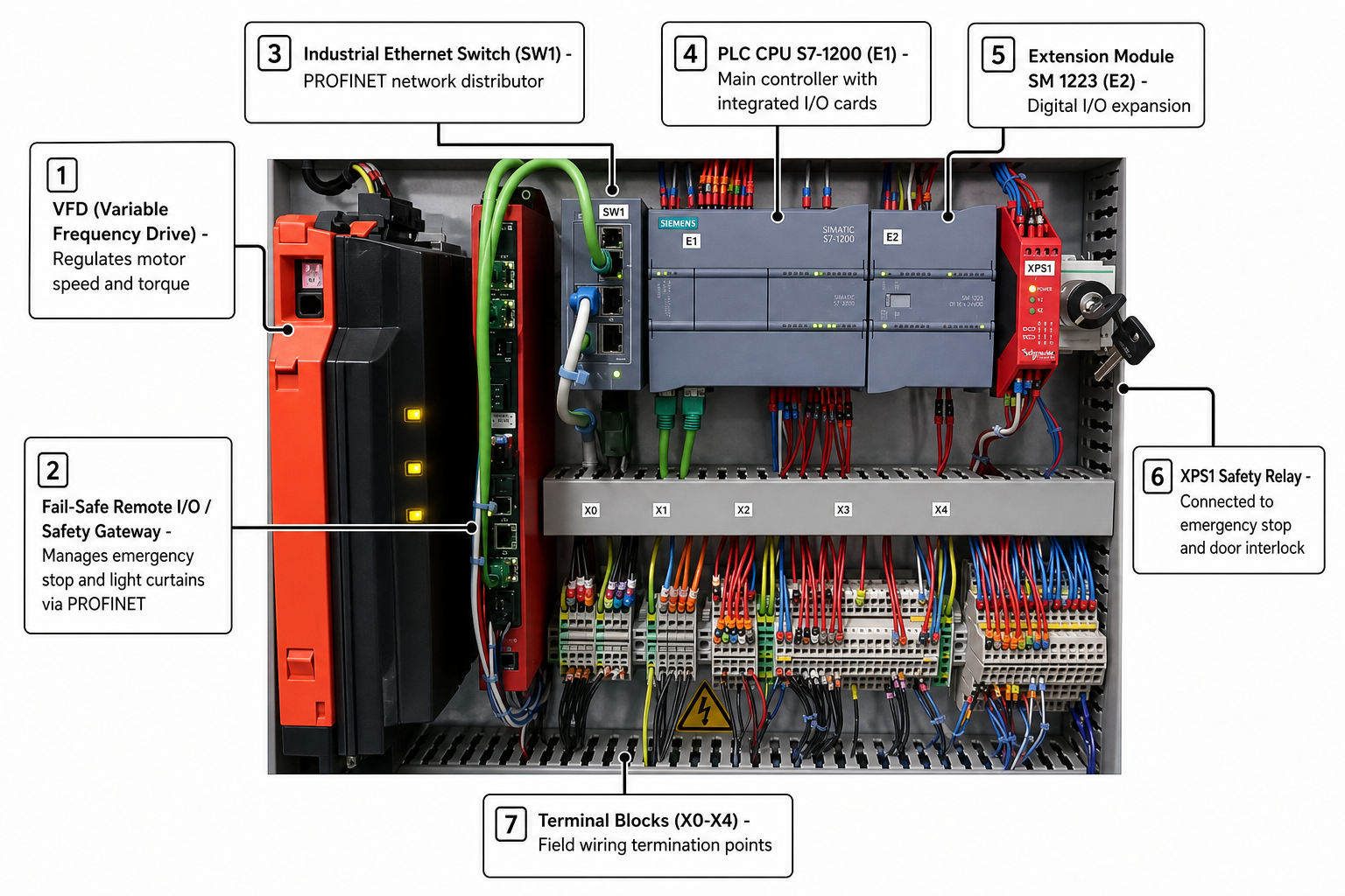
PLC Hardware Architecture
Modular Design
Modular PLCs allow hot-swap of I/O modules in some product families (e.g. Siemens S7-1500 with I-Device). Safety-rated modules carry TÜV certification and integrate seamlessly with standard modules on the same backplane.